|
Home |
|
Contact |
|
Service List |
|
Project List |
|
Publications |
|
Other Material |
|
Related Links |
|
Phone: Lancs 825064 E-mail: martin_AT_mjb-rfelectronics-synthesis_DOT_com |
|
To contact me : |
|
PLL Course Examples |
|
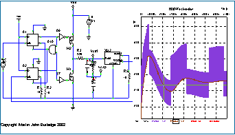
The simulation based exercises allow the student to carry out PLL measurement exercises prior to attending the lab sessions. The exercises also familiarize the students with basic frequency synthesizer operation. The material consists of a set of exercise notes and a set of working circuit files. In addition, MATLAB / OCTAVE scripts are included to assist in calculation of loop component values. They also allow the student to produce analytical response plots. The key exercises allow the student to experiment with VCO gain measurement, charge-pump measurements, phase-frequency-detector operation, step response simulations, and transfer function simulations. Where appropriate, simulations are referred to the associated practical lab sessions. The contents page, aims and objectives, and selected plots are shown here. |
|
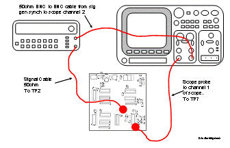
This is the first of the ‘at-presence’ lab based modules . In this lab session the students carry out basic functional measurements on the board. The primary focus of the session is to verify that the system is operating correctly. In addition, the activities familiarize the students with typical measurement setups. The session starts by verifying correct voltage levels and then moves onto monitoring signals generated by various sections of the synthesizer system. More details are shown here. |
|
Simulation based exercises |
|
Module 1: Basic board measurements |
|
Introduction: The PLL demonstrator course was initially developed to provide a practical platform for a student to become familiarised with basic PLL / Frequency synthesizer operation. The course material comprises of two key parts, consisting of a set of simulation exercises and a set of corresponding practical lab based exercises. The material provides all the basic theoretical background to support the experiments. The simulation exercises were developed for use in the B2SPICE simulation package and were included to allow the students to familiarise themselves with the experiments prior to attending the lab sessions. The hardware board primarily consists of a 74HCT4046 PLL chip in conjunction with various counter IC’s controlled by DIP switches. One motivation for using separate chips was to allow the student to become familiar with typical components included in a frequency synthesis system. Another version of the hardware that employs programmable logic and has some more advanced measurement features has also been prototyped. The key experiments cover, frequency step response, transfer function measurements and VCO gain measurements. Many of the measurements were automated so that the user could import measurement values directly into a predefined spreadsheet. A subset of the material was also adapted for use in a remote access laboratory. Further details of the work can be found on the publications page. For an at-present taught course, each module lasts approximately 3-4 hours, including time to present the initial background theory. However, it is recommended that the students also familiarise themselves with the basic theory prior to attending the lab sessions. The material can also be adapted for remote access delivery. The key elements of the course are summarized below. The links point to abridged versions of the module notes. A further overview of the material is shown here. |
|
Course Structure |
|
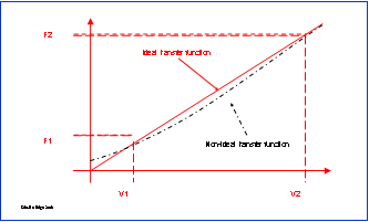
The VCO gain is estimated using two techniques. One involves manual control of the VCO input terminal via the voltage from a resistive divider network . This is carried out with the PLL in an open loop mode. Another method monitors the VCO control voltage for different feedback divider settings. For this particular system, this provided a less sensitive measurement. In both situations the output frequency for different voltage settings is recorded. The measured values are entered into a predefined spreadsheet that plots the VCO transfer characteristic. Students are asked to investigate and comment upon the change in VCO gain over the operational range. More details are shown here. |
|
Module 2: VCO gain measurements |
|
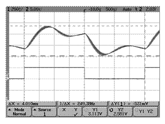
This lab session allows the student to become familiar with a frequency step response of the frequency synthesizer system. The tests are carried out at different frequency divider settings and the students have to estimate the damping factor and natural frequency. MATLAB / OCTAVE files are included to assist in the evaluation of these parameters. More details are shown here. |
|
Module 4: Frequency step response measurements |
|
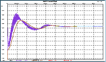
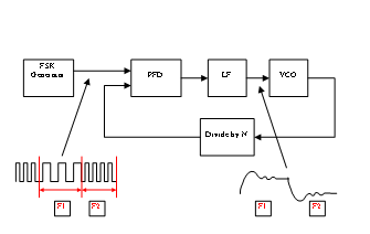
The phase transfer function of the frequency synthesizer is measured by applying a frequency modulated signal to the reference input of the system. During the measurement process the students are asked to increase the modulation frequency and then measure the response at the loop filter node. Measurements are automated data can be imported directly into a spreadsheet. More details are shown here. |
|
Module 3: Phase transfer function measurements |
|
MJBRF-Electronics Dr. Martin John Burbidge |
|
Electronics and RF, research, development and prototyping. |