|
Home |
|
Contact |
|
Service List |
|
Project List |
|
Publications |
|
Other Material |
|
Related Links |
|
This page contains further pictures and videos and notes related to RF microwave and mmwave experiments. The items on this page are all experimental, and all of them are ongoing as and when I get the chance to work on them. |
|
More pictures related to set up and measurement of experimental 60 GHz multiplier (see project list page for additional details) |
|
RF and Microwave Experiments |
|
For more information: |
|
E-mail: martin_at_mjb-rfelectronics-synthesis_dot_com |
|
Various pictures showing the construction of the diode multiplier and horn antenna are shown below. |
|
MJBRF-Electronics Dr. Martin John Burbidge |
|
Electronics and RF, research, development and prototyping. |
|
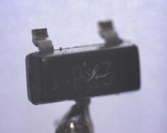
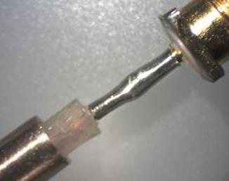
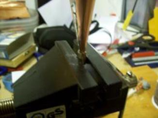
Diode soldered to coax inner prior to cleaning |
|
Diode soldered to coax inner. |
|
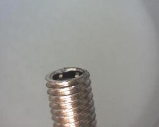
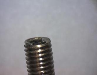
Diode and coax assembly inserted into threaded rigid outer conductor. Note threads are to allow an adjustment collar to be added to the horn antenna (see below). |
|
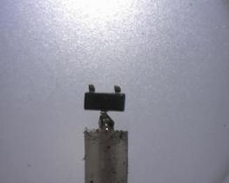
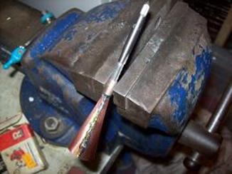
Diode soldered into outer conductor after forming the pins. |
|
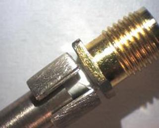
Soldering SMA inner to other end of the coaxial assembly prior to filing, cleaning and adding extra dielectric material. |
|
SMA pushed back into outer conductor prior to soldering. |
|
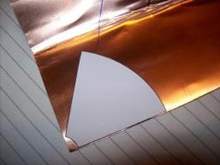
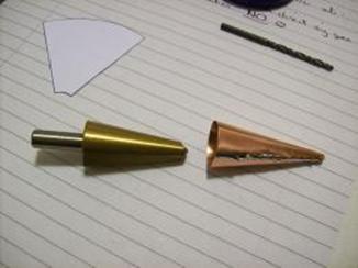
Marking out cone template. |
|
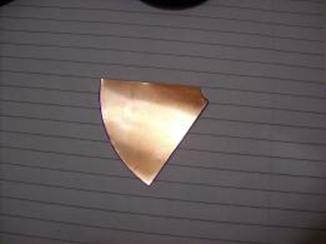
Cut out cone blank before forming. Note cone is constructed from 0.1 mm copper sheet. |
|
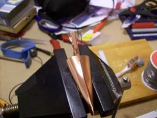
Forming cone, soldering and re-forming. Excess solder was removed from the inside of the cone and the end of the cone was removed before soldering to the adjustment collar. |
|
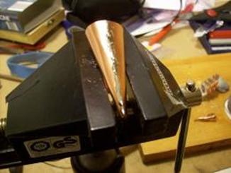
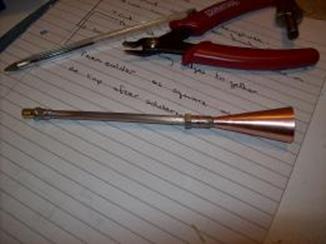
Cone inserted into in to threaded adjustment collar aligned and then soldered. |
|
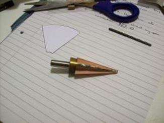
Final assembly. |